Harbor Freight Greenhouse Assembly
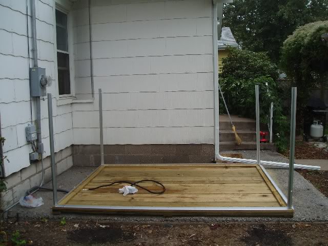
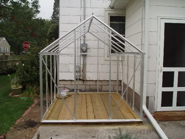
Step 1
Parts #rd 34 (2) The longer pieces on Bottom of frame
Part # 16 Left (Back of Greenhouse) of Bottom Frame
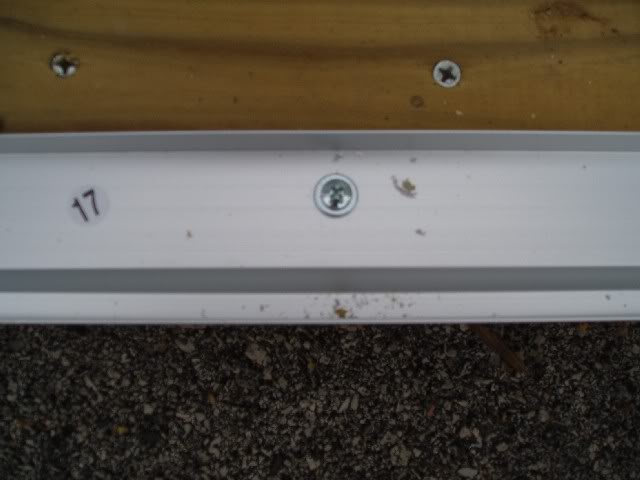
Part # 17 Right (Front of Greenhouse) of Bottom Frame
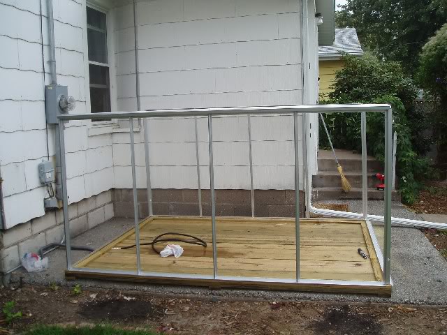
Parts #1 (2) Standing Upright (Looking in from where your door will be) in Opposite Corners: Front Left and Back Right
Parts # 29 (2) (Looking in from where your door will be) Standing Upright in Opposite Corners: Front Right and Back Left
Note: All bolts were "hand tightened" in the beginning and will all be fully tightened later.
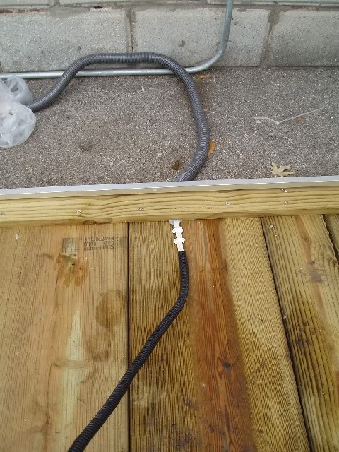
Step 2
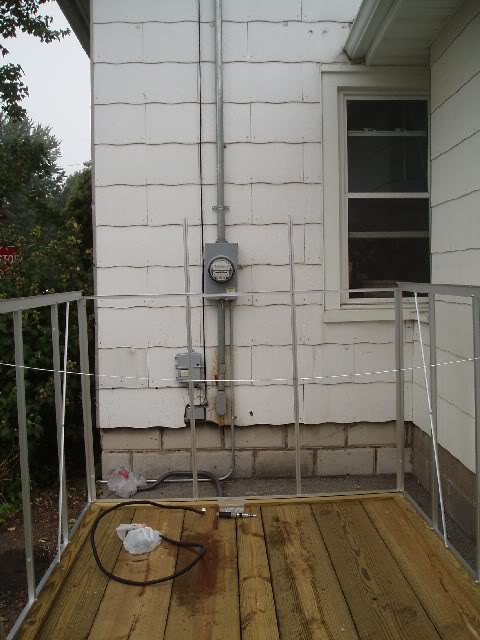
Image shows how Romex wire was brought into the Greenhouse. A channel was hand chiseled and silicone caulked. Depending on how you decide to build your wooden base, etc. results will vary. This is how I chose to build mine.
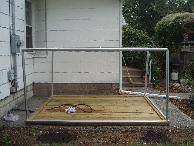
Step 3
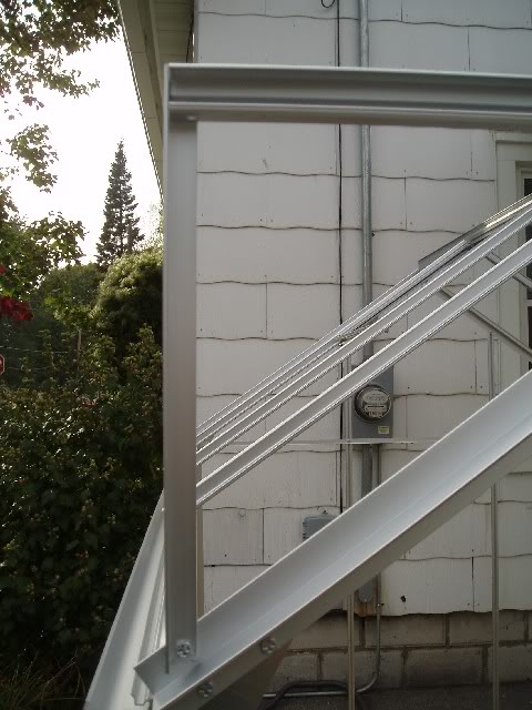
Upper side rail gutters have been installed (2) # 36�s. All bolts are still being hand tightened.
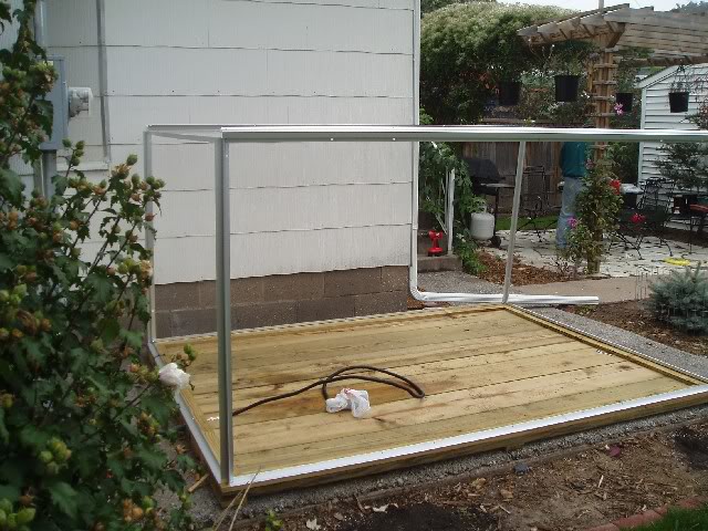
Step 4
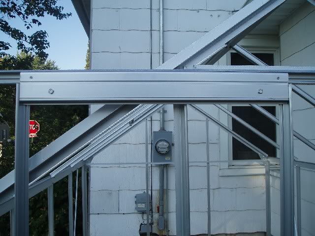
Part # 21 attached to # 29 and # 1 on back wall of greenhouse. The flange is on the inside of the frame with the flanged "lip" being on the bottom.
Step 5
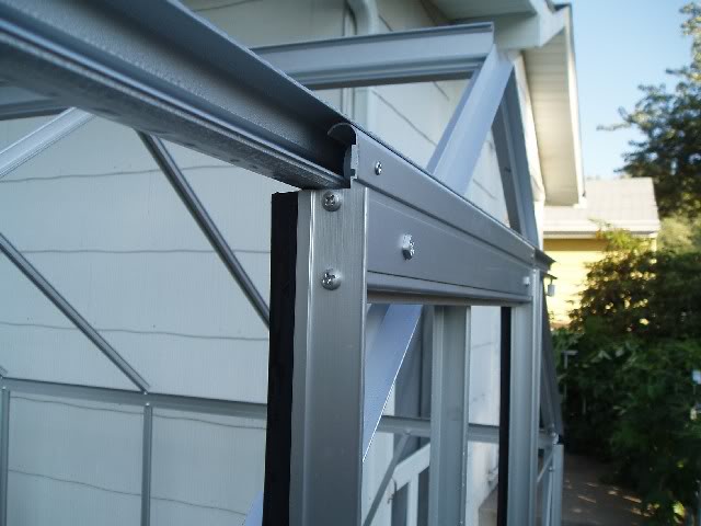
You�ll be installing (6) # 10�s. They will bolt to the bottom frame as shown in the first photo and they will be secured using the T-bolts on the top of your frame (part # 36) by sliding them into the channel located on each # 10. ***VERY IMPORTANT*** at this point you�re going to need to slide an extra T-Bolt into four of you # 10�s before tightening up the T-bolt on your # 36�s. This extra T-bolt will later be used to attach to your cross bracing supports #�s 22 (4). This is a step not mentioned in the directions. The next series of photos will show all of this.
img src="http://img.photobucket.com/albums/v280/Cultivar/Harbor Freight%
20Greenhouse Assembly/HarborFreightGreenhouseAssembly005.jpg">
Here�s showing one of the cross braces and why you slid the extra T-bolt in. The next Photo will show you which of the # 10 pieces to slide the extra T-bolt into.
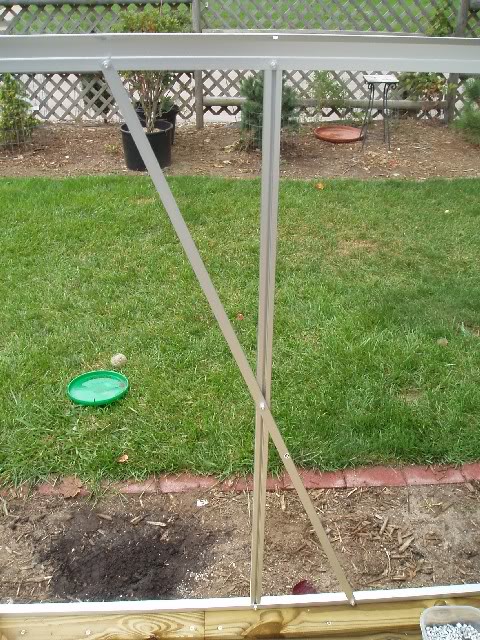
(Showing which # 10�s the extra T-bolt was slid into for future task of assembling the braces (# 22�s))
Step 6
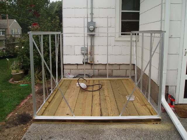
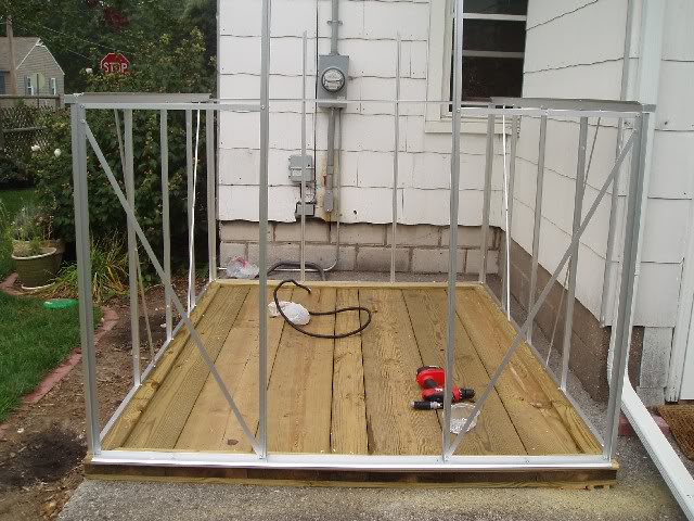
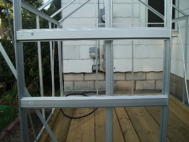
Photo of pieces # 8 and # 9 installed left to right repectively on back side of greenshouse. These are the two long pieces standing upright. We tied a temporary string to hold the front uprights together at this point.
Step 7
It was at this time we decided to secure the frame to the floor of greenhouse. You may want to use your own
judgment as to when this step is necessary, however we realized at this time we needed to secure the Frame to the wooden base.
**Note** Had we secured the frame to the base in the very beginning as the instructions recommend, we would have to undone it and done it all over again. We used Pan Phillips Zince 10 x � with Zinc Flat Washers # 10 to secure it. The aluminum is pre-drilled but not the wooden base.
Now that the frame is secured to the wooden base it�s now time to "using a level" go back and make sure it is all square and then go back and tighten every bolt.
Step 8
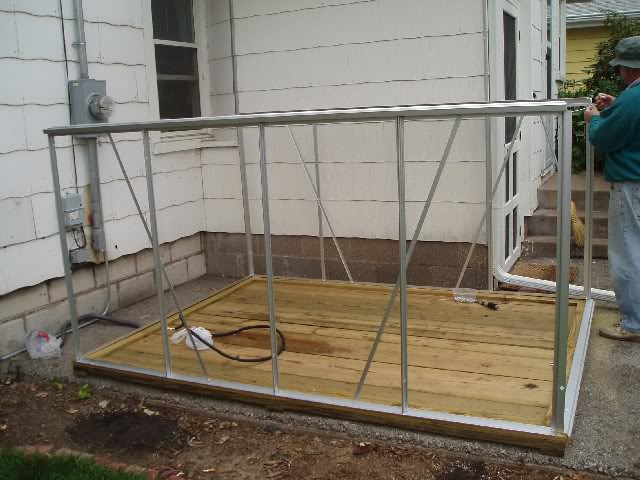
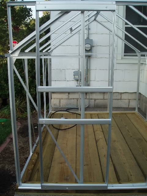
Front diagonal braces (2) # 25�s are secured to front of greenhouse which at this point really stiffens up the entire thing.
**Note** After these braces are put on, the Front ALSO should be square. We had a temporary piece of string holding the front together. At this time our temporary rope was removed. The entire frame is extremely rigid at this point.
Step 9
There�s a lot going on here�
(2) # 23�s and # 6 and # 7 are going to be attached. BOTH # 23�s will be attached FLANGE UP AND FACING OUTSIDE. For #6 and #7 you�ll need to attach them by undoing the bottom bolts on the cross slants and by securing #6 and #7 respectively from RIGHT to LEFT. Photo shows this work as being finished.
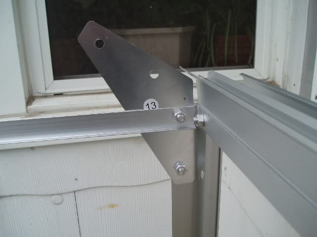
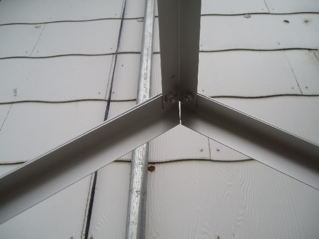
Step 10
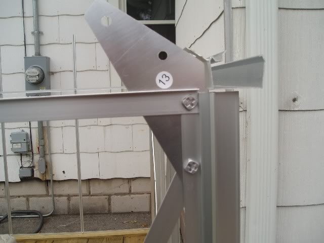
You�ll be installing (4) # 13 parts. (2) will be installed in the front and (2) will be installed in the back. The first photo shows how these parts are attached to the front and the second shows how they are attached on the back. They fit in conjunction to the pitch of the roof in each corner.
Step 11
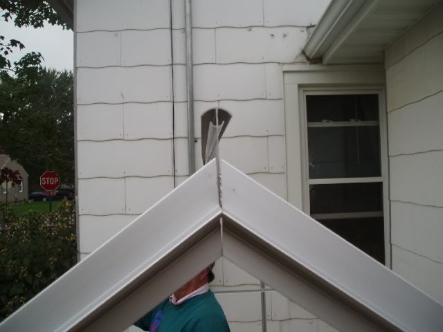
(Preparing "Crown Beam" part # 35 with (6) # 11�s). ***NOTE*** At this time again, you�ll need to slide an extra T-bolt into two of your #11�s. The #11�s that needs the extra T-bolt are the ones being used for your pop up vent. See illustration Page 5 Figure B for exact placement.
These series of photos show a generic illustration of how the Crown Beam and it�s componets are attached.
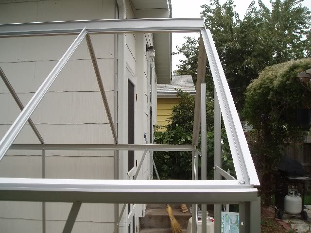
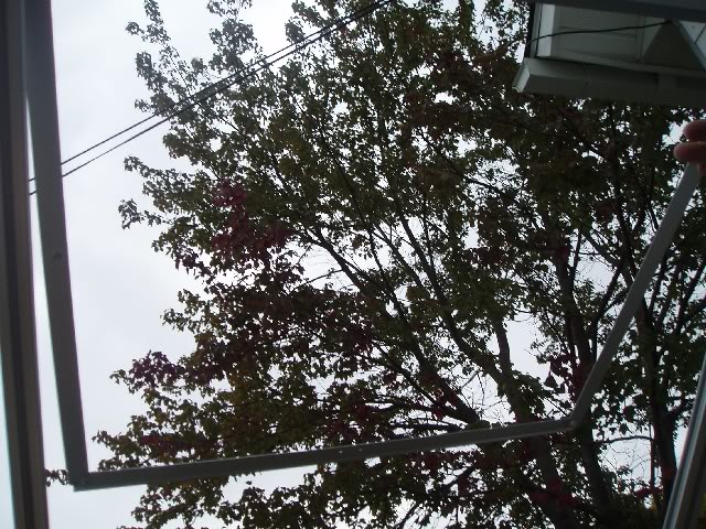
Step 12
Photo of completed roof frame.
Step 13
This is a photo of the CROWN BEAM in the FRONT of the GREENHOUSE. This Photo shows the channel in which part # 33 slides in. Part # 33 is the louvering mechanism for your pop up vent. See illustration Page 5 Figure B for further visual understanding.
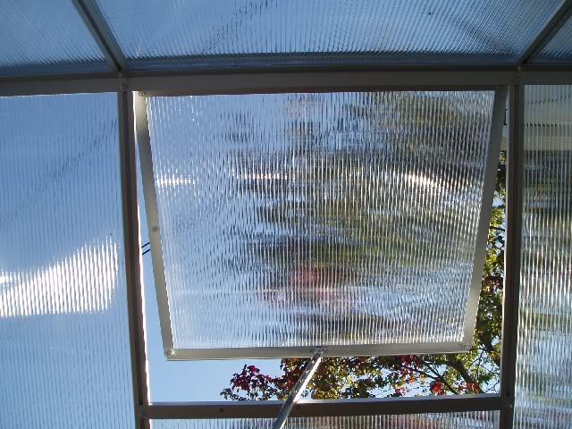
Step 14
(Not a good photo). This shows how the pop up vent is put together using parts #30 (2) which are held together by part # 32 (bottom of vent).
Here�s another photo showing the same thing I just took.
Step 15
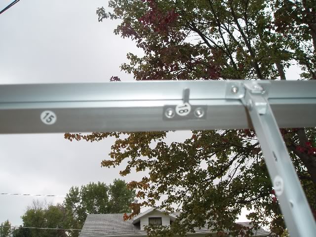
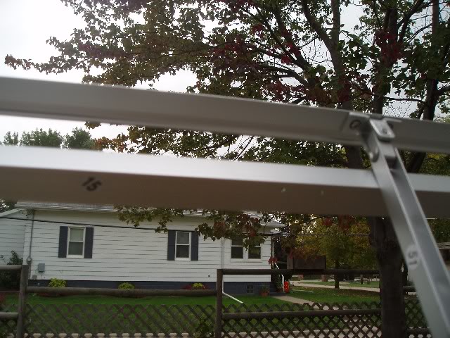
The next two photos show the installation of part # 15 and the very small part # 18 which will screw into part # 15. These photos will also show part # 51 and how it is installed.
#15 will attach between your (2) # 11�s that you EARLIER (damn these instructions!) slid the extra T-bolts into. Then of course you�ll attach part # 18 as shown. Part #18 is what holds the louver arm.
And another view
Step 16
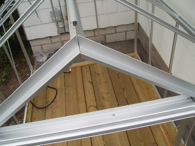
Part # 12 will be attached first to the holes between the top of the door frame in order to mount the door track, piece # 14. Part # 14 mounts to piece # 12 with slide in T-bolts. Part # 12 was attached first.
Photo taken from above after both parts were installed.
Step 17
Installing part # 14 (Long Bar that connects to part # 19) Part # 19 was installed first. Two photos illustrate how this installation looks.
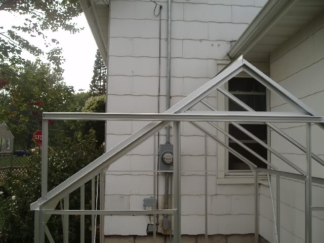
And a close up of Part # 19 as to how it is secured (Photo detail of # 19).
DOOR ASSEMBLY
Using Sheet Metal Screws (packet #44) screw directly into the allotted channel for each frame piece. Going from top of door to bottom.
Photos going from top to bottom
#24 which is underneath # 31 (I missed a photo but you�ll just have to figure out what I mean by saying #24 is UNDERNEATH # 31)
#26
#26
#27
#20 on LEFT SIDE
#28 on RIGHT SIDE
Photos:
This photo shows Top of Door. Part #31 on top of #24 (#24 is put on first)
This photo shows left side of door (#20) 2 sheet metal screws holding #31 to #20.
This photo shows both parts #26
These next two photos shows part #27 from the front and from the side. NOTE: This is the only part of all of the door parts that only is held in place with one sheet metal screw per side (see photo).
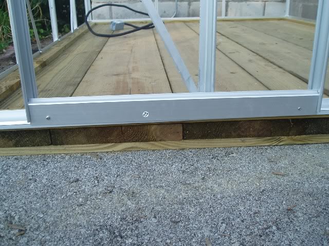
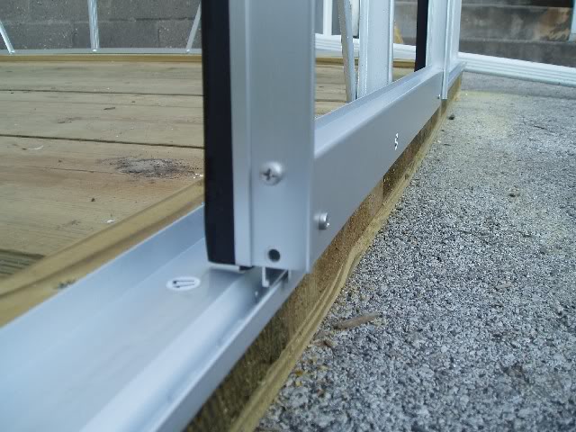
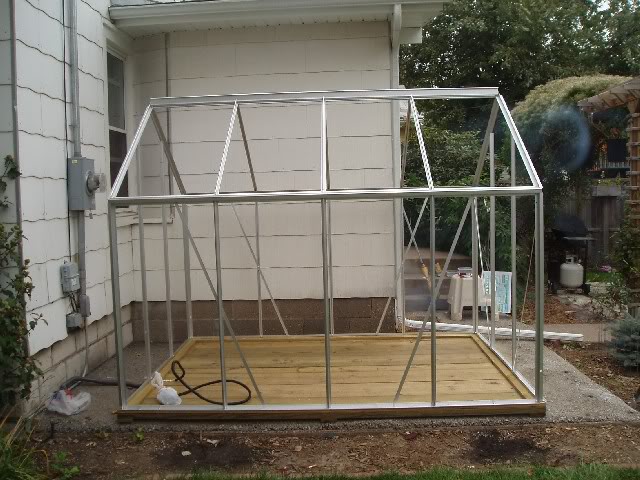
Photo of Completed Frame With Door
PANELS
We taped them (temporarily) on the inside to various parts of the frame and panel as needed to draw the frame and panel together then every panel was silicone caulked (clear silicone) from the outside. Just as a note, I used 9 tubes in total. You can use whatever kind of silicone you like but I went for the 50-year stuff. I�ll remove the tape tomorrow. Here�s my finished product.
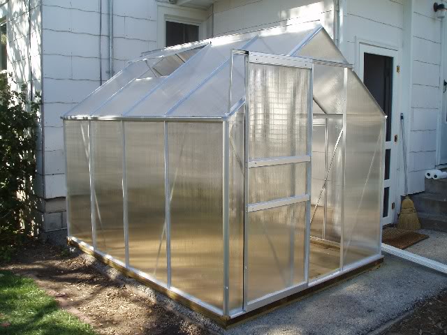
I hope this makes life easier for many of you.
Dax